ing.-büro bechler halle
Software-Entwicklung
nor
-VerySimpleLogicSimulator
Tutorial
nor is not suitable to develop commercial Circuits but to simply and quickly simulate and verify all
that Schoolbookstuff dealing with basic logic Elements. So you won't
find big libraries with a lot of Circuits in it with the need to
learn their Handling and Usage not even Autorouting for automated
Wiringlayout.
Only five Elements NOR, NAND, OR, AND and XOR and some additional
Tool devices for generating, storing and visualizing Inputs and Outputs
are available.
We do not use an academic claim in the arbitrary editable Tutorial's
Samples following but to become familiar with the Theme and the usage
of the application.
If you need some more, you build it by
yourself in using the native Elements, add In- and Out-Clamps and
then use it in unlimited even nested Copies in other Circuits.
All your Circuits are saved in Definitionfiles which are simple
ASCII-Files editable with every Textapplication like Window's Notepad.
Setting a bit-Value is done by a Mouseclick, to 'wire' Clamps drag it,
and your Circuit will always immediately reflect its Consequences.
If you do not have a nor -
Very-Simple-Logic-Simulator Application on your Computer you may
want to download nor
for Windows-XP/Vista/7/10/11 first to play
with the Samples: DOWNLOAD
(1,6MB)
(Once installed please make sure that you set one of the three Folders in
Menu/File/Options to the Samples-Location that is by default:
"C:\Program Files\ibh\nor\Samples")
Unser nor - Very-Simple-Logic-Simulator für Windows-XP/Vista/7/10/11 ist ein sehr einfach bedienbares
Logik-Simulations-Programm für
den Informatik-Unterricht und
das Selbststudium.
Mit der Anwendung können keine kommerziellen Schaltungen erstellt
werden.
Aus NOR, NAND, OR, AND u. XOR-Elementen werden hingegen schnell
funktionsfähige Schaltungen "aufgebaut" und ausprobiert.
Die Schaltungen werden mit der Maus editiert und reflektieren stets
ihre aktuellen Zustände.
Die eigenen Schaltungsentwürfe werden in Textdateien gespeichert und
können anschließend in anderen Schaltungen als Module verwendet werden.
Die Verschachtelungstiefe ist dabei beliebig.
Für die entstehenden Baum-Strukturen stehen Übersichten zur
Verfügung.
Es können Zustandstabellen angezeigt werden.
Die erstellten Modul-Definitions-Dateien können ausgetauscht und in
Modul-Bibliotheken verwaltet werden.
Schüler können verteilt an unterschiedlichen Aufgaben eines Projektes
arbeiten und in beliebig vielen Fenstern Schaltungen gleichzeitig
anzeigen und editieren.
Es werden einige zusätzliche "Tool-Elemente" angeboten, um
Standardaufgaben zur Speicherung und zur Ein-/Ausgabe zu vereinfachen.
Die im folgenden Tutorial verwendeten, beliebig editierbaren Beispiele
erheben keinen akademischen Anspruch, sondern dienen lediglich dazu,
mit dem Thema und der Bedienung des verwendeten Programms "nor"
vertraut zu machen.
Falls Sie noch nicht nor - Very-Simple-Logic-Simulator
für Windows-XP/Vista/7/10/11 installiert
haben, können Sie hier die aktuelle Version 'downloaden' ( DOWNLOAD
(1,6MB) ), um die Beispiele
direkt aus dem Tutorium heraus aufzurufen.
(Bitte stellen Sie sicher, daß
einer der drei Vorgabe-Ordner unter Menu/File/Options auf das
Verzeichnis für die Beispieldateien gesetzt ist. Standard:
"C:\Programme\ibh\nor\Samples")
Content
Memorize following Functions to
create or delete Elements on
your 'Board':

Insert an external Input-Clamp on the left Side of the Board so that your Circuit can be used by other Circuits.
▸

Insert a Standardelement (NOR, NAND, OR, AND, XOR, Source, Meter, 7-Segment-Display, RAM256x8, Shift-Register, Random-Generator, Clamp, par. In-/Output). (also: [Ins])

Insert a self-defined, 'self-made' Circuit as Element from its Definitionfile. (also: [Alt]+[Ins])

Insert an external Output-Clamp on the right Side of the Board to later connect with other Circuits.

Use corresponding Buttons to delete the current or marked Elements. (also: [Ctrl]+[Del])
Get Summeriesof the available Elements with the three following Sample-Files:
Make yourself familiar (play around) with the five native logic Elements i.e. with _The Logical-Elements_.nor :
▾
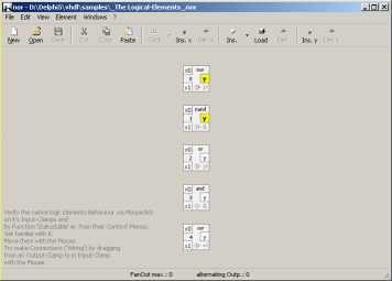 The logic Elements
These are the available, ready-to-use Tool-Elements for various Tasks _The Tool-Elements_.nor
:
 The Tool-Elements
and here are several 'Clones'/'self-made'/nested
Elements _Several
Clones_.nor :
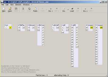 Several 'Clones'
Introduction Content
All current computing machines are huge sets of logic Elements with at least NOR(not or)- or NAND(not and)-behaviour
which has been realized with several Techniques during time. For
studying purposes you might get a limited amount of them in small cases
with jack plugs for the connections. The nor - Very-Simple-Logic-Simulator offers you to connect an unlimited amount of such Elements in its reusable 'virtual' circuits.
Here are some examples for logic Elements in the real world.
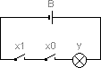
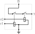
Simple Switches-array with AND-Behaviour:
The Output (Lamp "y") of that circuit will burn (go "high") if Input-Switches "x0" and "x1" are closed ("high") and a battery "B" is connected.
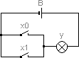
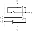
Switches-array with OR-Behaviour:
It's Output will be "high" (Lamp "y" burning) if at least one of the Input-Switches "x0" or "x1" is closed.
The Inputs of above circuits must be set manually by their switches and Output is indicated by a light.
But we intend to connect such circuits for getting more complex
variations. Thus we extend them with the ability to be set in their
native way: electrically. To do so we use switches that can be operated
by electromagnets (relais).
An AND-Module with relais:
If both relais are driven via Inputs "x0" and "x1" with a
current from a voltagesource also connected to "B" then Output "y" will
be set "on" (or "high") too.
Here a variation with OR-Behaviour:
Setting one Input "high" suffices to fire Output.
In practise you will find circuits using semiconductors as switches gathering a huge amount of them on one substrat.
NAND(not and)-Gate with two transistors and a resistor as voltage divider:
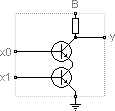
Since not both transistors are driven output "y" remains "high" (on "B"-voltagelevel).
NOR(not or)-Gate with transistor and two diodes:
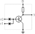
Output will go "low" (ground-voltagelevel) if its base is set
via one of the diodes (which isolate the inputs against each other).
Notice: In nor - Very-Simple-Logic-Simulator circuits you might miss that above shown wiring with currentsources ("B" and "Ground"-Clamps)
having in mind a Circuit with a "+" and a "-" connection like the shown "Battery-Switch-Lamp"-Circuits.
Keep in mind that in all hereafter discussed circuits all Gates and circuits needs
a connection to a Voltage/Current-Source.
Because of that fact there is no necessity to explicitly draw them.
Also we will call a "Clamp" being in a "high" State if it's logical
Value is "1" otherwise "low" or "0" independently of how it will
be electrically represented by a potential or a current.
High-stated Clamps and Wires are shown in different Colors and
Fontstyles.
Here is how nor - Very-Simple-Logic-Simulator represents above NOR-Gate with high output due to both low inputs:
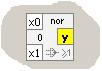 inserted with button from the nor - toolbar
While playing with the examples of that Tutorial have in mind (if its
not clear to you yet) that your goal is: "How to construct an universal
machine to take logic decisions depending on various inputs and rules".
That might deal with the settings of a lot of electric switches or on
some information from equity researchs. Its a matter of naming it.
Example 0: If you don't have any Idea on handling binary Digits Content
Samplefile: FirstStep.nor
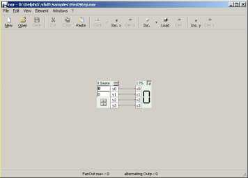 FirstStep.nor
In that Sample you see two of the Tooldevices for generating and
visualizing Inputs and Outputs.
The left Source-Element
produces Output on its Clamps according to the Value in the Editfields
indicated by you.
The upper Input-Field of the Source-Tool-Element contains the
Outputvalue in hexadecimal, the lower one
in decimal and the four Clamps 'y0'...'y3' in binary Notation.
The Seven-Segments-Meter-Tool-Element
on the right is connected with the
Source via four "Wires" representing a four-Digits binary Number.
(Note: The topmost 'Clamps'
labeled 'x0' resp. 'y0' represents the least significant digit
of their values. So reading is always done from top to bottom.)
The Source-Element enables you to generate Input-Values in four ways:
- Focus the upper Inputfield and write in a hexadecimal Value via
Keyboard
- Focus the lower Inputfield
and write in a decimal Value "
- Use the Buttons (belonging to a Scrollbar as you will see later) to
adjust an output-Value
- or click with the left Mousebutton on one of the four output-"Clamps"
of the Source to switch it on("1") or off("0")
Trying all possible Settings you will get the following Results:
decimal
(10 Symbols)
|
hexadecimal
(16 Symbols)
|
binary
(2 Symbols)
|
0
|
0
|
0
|
1
|
1
|
1
|
2
|
2
|
10
|
3
|
3
|
11
|
4
|
4
|
100
|
5
|
5
|
101
|
6
|
6
|
110
|
7
|
7
|
111
|
8
|
8
|
1000
|
9
|
9
|
1001
|
10
|
A
|
1010
|
11
|
B
|
1011
|
12
|
C
|
1100
|
13
|
D
|
1101
|
14
|
E
|
1110
|
15
|
F
|
1111
|
As you see with the ten Symbols from the decimal Notation you can count
from 0 to 9. (Please keep in mind that every Counting starts with "0"
not with "1".)
If you want to count further on you will begin again with "0" and
indicate that fact in writing a "1" one digit left to get 10. So with
the ten different Symbols in the decimal System you can count from 0 through 9 on one digit.
Then you need a new digit whose value is ten times the first one due to
your ten available Symbols.
Now try to count with only two instead of ten Symbols.
You count: 0, 1, now your Set of Symbols is at its End similar to the
Situation counting until 9 with a decimal Symbolset. So you react in
the same way as mentioned above, beginning again with 0 and adding a
"1" at the next digit left resulting in "10". To count one more time
you again use the right digit resulting in "11".
Because you only have two Symbols you earlier need a new digit in
comparison with the ten-Symbols(decimal)-System. Also each new digit in
that binary-System has an only two-times (instead of ten-Times) Value
of its antecessor.
The binary System is used in computing Machines because it is much
easier to represent only two different Values than ten. On the other
Hand you need more digits to describe the same Value.
Keep in mind: To represent a given Number you can use an arbitrary Set
of Symbols for Example ten or only two. Each time you used all Symbols
there is the need to begin with the first Symbol (the null-Symbol) on
the same digit and to use a new digit which is <amount of
symbols> ^ <place of the digit> times stronger than its
antecessor.
For Example the "1" in the decimal Number 10 has the value 10^1 = 10
(digits are numbered from the right to the left beginning with 0 at the
rightmost digit).
Analogues the "1" in the binary Number 10 has the (decimal) value 2^1 =
2.
Last, what about the middle column in the above table titled
"hexadecimal"?
As you mentioned from the above you need four binary digits to count up
to decimal 15 but need two digits in case of decimal numbers. Because
the first basis on multiples of 2 and the second on multiples of 10
there is no simple way to fast compare binary and decimal numbers on a
glance if
you do not want the necessity of a lot of digits. So you will probably
use another numbering-System to express the binary values also basing
on multiples of 2. The usual way is a numbering-System based on a
multiple of 2 namely 16, what is called a hexadecimal(16) System.
Dont worry its much easier than you think. For Simplicity we use the
Symbols "0" to "9" from the decimal-System and add 6 more Symbols
taking the first 6 Symbols from another well-known Symbol-Set, the
Alphabet. Now we are able to count from 0 to 15 (decimal) or from 0 to
1111 (binary) or from 0 to F (hexadecimal) with the need of only one
digit in the hexadecimal case.
Keep in mind: we were dealing with the question of how to represent
numbers with different Symbol-Sets which has no influence on how to
calculate with them.
To distinguish between the several Notations you will often find
additional Symbols like a "d" for decimal, a "h" for hexadecimals or a
"b" for binary Numbers or something else. d, h and b are used in the
current Application.
Use the Example-Circuit to make yourself familiar with that different
Symbol-Sets because otherwise there is no chance to understand anything
in logical Circuits. Mention also that the Question which Symbols you
use is arbitrary. The two States of binary digits may be expressed by
"0" and "1". But you can also use "off" and "on" or "low" and "high" or
"white" and "yellow" (as used by default in our nor-Application) or
"false" and "true". The latter gives a hint on why binary
numbering-System is very well suitable for expressing logical cohesions.
Example 1: The five available native logic Elements Content
Samplefile: Logical-Elements.nor
Open the Sample-nor-Descriptionfile "Logical-Elements.nor" from the
folder "Samples" whose default Position is "C:\Program
Files\ibh\nor\Samples".
That Samplefile shows all five native logical Elements you can use to
build any Circuit from.
All that Elements come with two Input- and one Output.-"Clamp".
Get familiar with its different Behaviours in Clicking on its
respective Input-Clamps titled "x0" and "x1" and observing the
resulting Values on the Output-Clamps titled "y".
Recognize the two Groups "ORs" and "ANDs". "ORs" changes their
Output(y) if one of their Inputs(x) is changed. "ANDs" changes their Output(y) only if both
Inputs(x) are changed.
In the Case of "NOR" what means "NOT OR" and "NAND" what means "NOT
AND" the Output is simply inverted. Notice that in the case of a "XOR"
(exclusive OR) Output is set to "1" if only one of the Inputs is set.
Notice: We discussed to add a
"NOT"-Element as a lot of Users will look for it. But in view of
Simplicity there is no need for it because you can use either a "NOR"-
or a "NAND"-Element to invert a logical Value.
To proof that we introduce "nested" Circuits here. Build your first
nested Circuit as follows:
- Get an empty nor-Window by Menu "File/New" or (if you want to
keep the Five-Elements-Example from above) via Menu "Windows/New
Window".
- Insert a NOR-Element on the empty Workspace or via Menu "Element/Ins(ert)
Type.../nor". (If you want to erase an Element make it the current one
by clicking on it or mark several Elements with the Mouse and use
Contextmenu or [Ctrl]+[Del] to delete them.)
- Cause the Circuit shall be used by other Circuits insert an external
Input-Clamp with or Menu "Element/Ins. ext. Input (x)".
- Insert an external Output-Clamp analogues with or Menu
"Element/Ins. ext. Output (y)".
- Connect the external Input-Clamp (x0) with one of the NOR's Inputs
(x0 or x1) while pressing the left Mousebutton on that external
Input-Clamp and dragging a 'Wire' to the NOR-Element-Input.
Notice: Dragging wires
(Connections) can be made only from Output-Clamps to Input-Clamps.
An Output-Clamp can possess arbitrary Connections to Inputs. An
Input-Clamp can only have one Connection to an Output.
- Connect the NORS-Output-Clamp (y) in a similar way to the external
Output-Clamp (y0).
Notice that the yellow indicated "high" Value of the NOR's Output (y)
is propagated to the now connected external Output-Clamp (y0) rightmost.
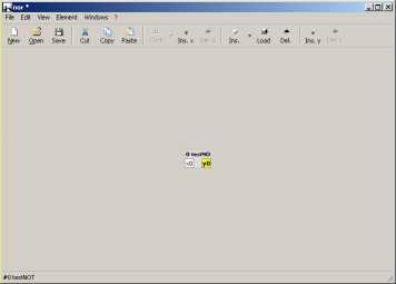
- Save your first Circuit in a File "testNOT" on Harddisk with Menu
"File/Save". Ready.
Your Circuit should look like that:
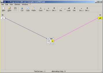 testNOT
Try your Circuit in Clicking on the external Input-Clamp (x0) leftmost
on your Workspace which leads to a "high" (yellow) State at that Clamp
and the connected Input-Clamp at the NOR-Element as well as to a "low"
(white) state at the Output-Clamps and vice versa.
Now use your Circuit in another Circuit:
- Again get an empty Workspace as described above.
- Insert a Clone of your just created Circuit with or Menu "Element/Load
Element..." and load File "testNOT.nor".
The result should be as follows:
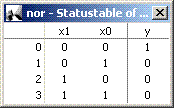
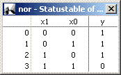
 Usage of testNOT
Verify the Bahaviour of that new Element as that of a NOT-Element by
Clicking on its Input-Clamp (x0).
If you list the Results in a Table with one Column for the Inputvalues
and one for the Output it might look like that:
Such a Notation is often called a
Status- or Truth-Table and is used to describe the Behaviour of a logic
Element.
Notice: Use the build-in
Function "Statustable"
to get Statustables of native or static, self made Elements
automatically via
Menu "File/Statustable" or [F3] for the whole Circuit (with both
external Input- and Outputclamps) or with "Elements-Context-Menu/Statustable"
(right mousecklick or [Ctrl]+[F3]) for the current (clicked) Element.
Notice: To see the Circuit of
a nested Element doubleclick on it or make it current and use "Open" in
its Contextmenu.
Following Table lists the available native Elements in nor - Very-Simple-Logic-Simulator with their Functions:
(Insert with Button resp. it's Listbutton from the nor - Toolbar or change behaviour with the element's Contextmenu.)
nor-Element
|
Name
|
Function
|
Statustable
|
|
NOR |
Inverted OR, inverted Disjunction, >=1 |
 |
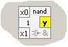
|
NAND
|
Inverted AND, inverted Conjunction, & |
|

|
OR
|
Disjunction, >=1 |

|

|
AND
|
Conjunction, & |

|

|
XOR
|
Exclusive OR, Antivalence,
=1 |
|
Example 2: Another Circuit Content
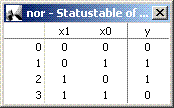
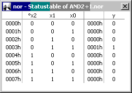
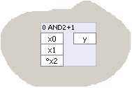
Samplefile: AND2+1.nor
Improve your Abilities in constructing Circuits with the following
Example where we assume that there is a need for an AND-Module with
three Inputs,
one of them with inverting Character.
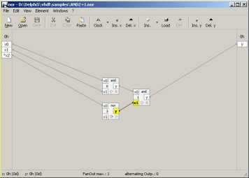 AND2+1.nor
Open the File "AND2+1.nor" from the Samplesfolder.
(Notice: If you have
difficulties to understand
its Functionality first have a look on AND3.nor
which is a simple AND-Module with three Inputs.)
As you may derive from its
Statustable ([F3] or Menu "File/Statustable") or by manually switch the
Input-Clamps with Mouseclicks, there is only one Input-Combination
(binary: 011, decimal: 3) that causes a high Output.
Notice: To change the external
Clamps' Labels (for Example to indicate the inverting Input x2 with '°'
as in the Sample), click with the right mousebutton on ext.
Input-Clamps or with a Doubleclick on the ext. Output-Clamps. Then
perhaps change the Width of the external Regions with their vertical
Splitters.
Finally use that Circuit in another one analogues to Example 1 what may
look like the following:
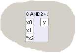
With Menu "View/Wide Clamplabels" or Key [F8] you can enlarge such
nested Elements (right image) due to wider Labels.
Example 3: Getting it
all from one Content
Samplefiles: nand_from_nors.nor
and nor_from_nands.nor
As we mentioned earlier all thinkable logic Circuits can be made from
that five Elementtypes described above. This is quite advantageous with
a view to Simplicity. But we can get a step further on in Simplifying
due to the Fact that all logic Elements can be produced from one
Element only if that have an inverting Character!
If you do not believe try Sample-Files "nand_from_nors.nor" and
"nor_from_nands.nor", view Statustables and compare them with their
native Types.
Notice: You can use the
Samplefile Testbench_Compare_NORS.nor
to easy compare different static Circuits. Here you will find another
nested Circuitry called "Compare8bit.nor" which is build up from
1-bit-Comparers defined in Compare.nor.
(Use the Clock's Listbutton
to get ongoing Input-Pulses.)
There are often several possibilities to realize a given logical
behaviour, among others varying in the number of Gate-Inputs to be
driven and the number of necessary State-Changes, having in mind an
electrical context.
The nors's Statusbar will announce
"Fanout max." and "alternating
Outp.".what can be interpreted as follows:
- Fanout max. gives
you a hint on how much Inputs have to be provided by a Gate's-Output
thus influencing the electrical Lay-out of a real Circuit. For example
if you intend to realize your Circuit from an ASIC
(Application-specified-integrated-Circuit) it might be advantageous not
to have a lot of Gates with low Powerconsumption and only a few one
with a high one due to high Fanouts. In that case you will probably
spread Outputs by several "Driver"-Gates thus getting Gates with
similar electrical Properties.
- Alternating Output
shows to you how much Gates change their Status during last Inputevent.
As if changing the Status costs Time due to the necessity of building
up and down magnetic Fields (Inductivities) and to move electrical
Charges (Capacities) you probably will lay out your Circuit having as
less as possible Changes if you want to obtain high Performance
(Frequencies).
Example 4: One-Bit-Adder Content
Samplefiles: ADD_half.nor
and ADD.nor
Now we will construct a first calculating Circuit which is able to add
two one-digit binary Numbers. That might be quite less. But as you will
see later that Circuits can be cascaded to calculate even higher Values.
At first open the nor-Description-File "ADD_half.nor" from the Samples'
Folder to learn the Principals.
 ADD_half.nor
Here is the Statustable (with [F3]) which you should recognize as 'exclusive-or'-Behaviour:
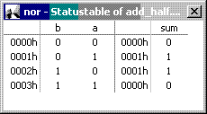
As you can see from the Statustable
the Circuit works fine in the first three cases where the Input (the
two Input-bits at external Clamps "a" and "b") is null or only one
Input is "1".
In the fourth case - both Inputs are "1" - an Overflow occurs which can
not be handled by that Circuit.
Also if there is an Overflow in an eventually preconnected Adder we
would not be able to handle it.
Because of that this Circuit is called only a "Half-Adder".
For propper Handling these additional cases we must enhance the circuit
as follows.
Consider at first (while using the Statustable) on which condition an overflow occurs. Which Element senses that?
Open File ADD.nor in another nor-Window (via Menu Windows/New
Window) and compare it with "ADD_half.nor". You will see an extension
of the Half-Adder to a "Full-Adder", being
able to additional calculate a "Carry"-Input from a preconnected
Circuit as well as to signal an occurring Overflow to a post-connected
Circuit via it's Output "ovfl".
This is our basic adding Circuit which we will now enhance to deal with
greater Numbers than One.
Notice: For moving the
external In-/Out-Clamps up and down on the Workspace's margins hold
down [Ctrl]-Key and drag them
with the Mouse.
Example 5: Two-Bit-Adder Content
Samplefile: ADD2.nor
Now lets proof whether we can add two
two-digits-binary Numbers while simply cascading two previously
described Full-Adders. Open File "ADD2.nor".
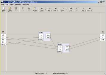 Add2.nor
Both embedded One-Bit-Full-Adders are enlarged with Key [F8] to show
complete Labelcaptions.
The upper one is responsible for adding the both least significant bits
("LSBs", from Input-Clamps a0 and b0) while the second Adder calculates
the most significant bits ("MSBs", Inputs a1 and b1).
If there will be an Overflow in the first Adder its Output-Clamp "ovfl"
will go high and this will be propagated to the seconds Adder-Input
"carry".
Remember our Example 0 where you learned that you can count up to three
with a two-digits-binary Number. Let us extend the Circuit so we can
add two real Bytes each consisting of 8 bits to allow an
eight-bit-Result or in decimal notation 255.
Notice: You may use the
Statustable-Function
[F3] to view the Behaviour of that Circuit. Try to
Sort the Table
on different Columns by Clicking on their Titlecaptions or to put it
into Windows' Clipboard via it's Context-Menu for further use in ie. a
Textdocument. (If you need a Bitmap
of the Circuit use Menu File/Print or [Ctrl]-[P] to copy one
into the Clipboard.)
You may search for associated
themes with Google.
Example 6:
Eight-Bit-Adder Content
Samplefile: ADD8.nor
Open File "ADD8.nor" and use
Function "Fileinfo"
available from Menu "File/Fileinfo" or Key [F9] to comprehend the
nested Circuits.
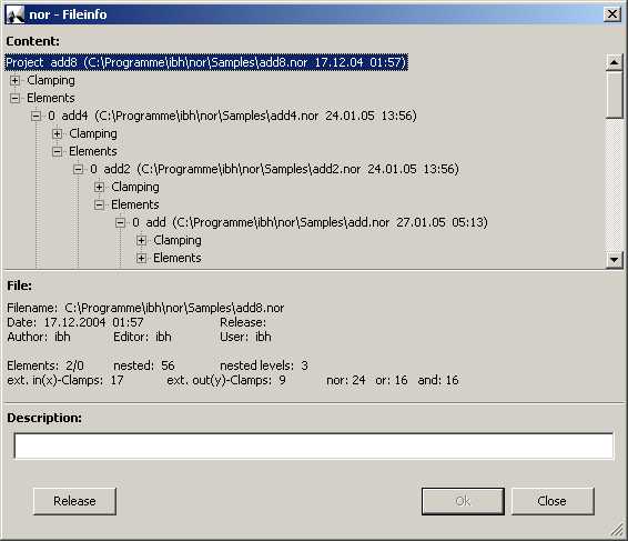 Add8-Fileinfo
The Fileinfo-Window is giving an
Overview about the Context of the nested Circuitry. In our Example
Add8.nor you can see in the upper third of the Window that it consists
of two four-bit-Adders out of "Add4.nor" which for their part are each
consisting of two two-bit-Adders as described in the previous Examples
each containing two Full-Adders.
(Notice: If you are dealing with HDLs [Hardware-Description-Languages]
such as VHDL compare the Sections "Clamping" [connections of In- and
Outputs] and "Elements" [what is connected] with the therein used
Notations.)
In the middle Section beneath several Projectinformations you'll find
that it needs 24 NORs, 16 ORs and 16 ANDs to receive a calculating
Machine able to add two 8-bit-Numbers (decimal 0...255).
Now use your new 8-bit-Adder to construct a simple Calculator as you'll
find in Calculator.nor :
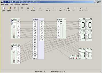 Calculator.nor
Do not be to much impressed by the
apparent complexity of the wiring. After a while you see that the Heart
of that
Circuit is only the known 8-bit-Adder whose two 8-bit-Inputs are simply
driven by two "Source"-Tool-Elements from the "Ins."-Element-List on
the
Toolbar or the Menu you became already acquainted with in Example 0,
thus giving the Opportunity to input Decimals as well.
On the right Hand of the 8-bit-Adder there are some "Meter"-
respectively "7-Segment"-Tool-Elements for displaying the Result in all
three earlier discussed manners (decimal, binary and hexadecimal). Try
also the Function of the One-bit-"Meter"-Element with it's "LED" beneath the Results-Display.
Now at first enjoy the Fact that you build up a Circuit being able to
Calculate for itself without using the Processors own calculating
capabilities as it is usually done, even the Result is restricted to
8-bit Numbers. If this is too less for you extend it like in Samplefile
"Calculator16.nor" . . .
By the way: We assume that you already discovered the additional
Elements in the "Ins."-Elements-List come along with the Toolbars -List-Button or the Menu
"Element/Ins. Type..."-List. In its second Section you'll find some
useful Tool-Elements
for simplifying Input/Output-, Display- and Storing-Tasks.
Some of them let you adjust their bit-Widths with an Up/Down-Button in
its right-upper-Corner. 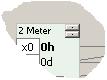
With regard to the 7-Segments-Elements at the same place there is a
Switch labeled "d" to add a Decoder for directly convert 4-bit Values
(decimal 0...15, hexadecimal 0...F) into hexadecimal digits.
Nevertheless you could also construct your own Decoder from the native
logic Elements. So this is for faster Working only.
A hint for Teachers:
To consolidate the understanding of the several ways to represent
Numbers you may perhaps let your Students add another
One-Bit-Meter-Tool-Element with its "LED" to indicate if the current
Calculator-Result is odd.
Example 7: Flipflop, one bit of Memory Content
Samplefile: FlipFlop.nor
Now its time for something new. All our present Circuits are static and
all bit-Status are volatile. If you switch a high-leveled Clamp,
representing a "1" it will at once change to "0" and nothing in the
Circuit will remember its previous State. Consider a simple Task like
Counting Events. Up till now we do not have a Solution.
In other Words: How can a Circuit memorize a former State?
Here it comes:
Open the Samplefile with the funny Name "FlipFlop.nor" from the
Samplesfilefolder consisting of only two NORs.
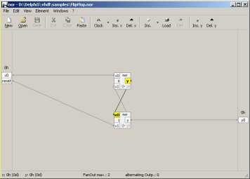 FlipFlop.nor
At first try the known Function "Statustable" with [F3]. The surprising
Result is a Message that a static Truthtable can't be displayed because
there is no clear Cohesion between Input and Output.
So let us try manually what happens.
Set the Input-Clamp "x0" from low to to high-Level ("1") thus forcing
the upper NOR's x0-Clamp getting high too.
Because of its high Input this inverting Element will set its Output
"low" ("0").
This Output is connected to an Input of the other (lower) NOR, thus
setting its Output consistently to "high" (1), forcing the second Input
of the upper NOR to become "high" too.
At that point be attentive what happens now if you reject your
"high"-Signal from the external "x0"-Clamp you have set at first:
Notice that all bit-States keep as just described despite the Fact you
switched off the Input!
Remind yourself our Goal to memorize bit-States. You just meet it.
Your Circuit obviously 'remembers' that you fired the external
Input-Clamp a time ago and due to its self-locking-mechanism it 'holds'
that Status even if you change the Input. The self-locking replaces the
lacking former Input that might be on only for a short timeperiod.
The Output will remain "high" ("1") until a complementary Input is set
via the other Input-Clamp here labeled "reset".
Now we are in the State to calculate and to memorize using only native
logic Elements which - as mentioned earlier - could also be replaced by
one of the both inverting Elementtypes NOR or NAND!
Notice: See also Samplefile Test-psc-spc.nor with parallel-to-serial and serial-to-parallel-Tranformation where our FlipFlop-circuit is used inside the serial-to-parallel-Converter.
Let's enhance our Circuit now for Counting.
Example 8: JK-Master-Slave-Flipflop
Content
Samplefile: 1bitCounter.nor
In that Example we will introduce the
Tool-Element "Clamp"
whose only Task is to make complex wiring more clear as you'll see in
this Samplefile.
Clamps can be represented in two manners to use them in different
Context. Switch between them with [F7]-Key or via their Contextmenu.
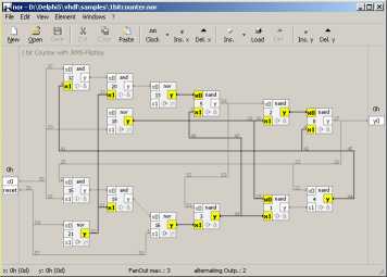 1bitCounter.nor
Expense some time to analyze that Circuit because its basic for any
counting-Problem.
You see two Flipflops memorizing alternately the otherones's State.
The rest of the Circuitry serves for it's ability to be resetted to a
known State what isn't defined from itself unlike in all previously
discussed Circuits.
Notice: For that purpose you'll find an
external Input-Clamp labeled "reset".
Each time you open a file with Clamps you labeled "reset" (by right-clicking
on the ext. Inputclamp) that Clamps will shortly set to "high" ("1")
during loading to force the Circuit to go into a defined State.
That functionality must be implemented by yourself like it is in
"1bitCounter.nor"!
Now try that Circuit in firing the external "x0"-Clamp (click on it).
What happens?
Each time Input goes "low" ("0") the ext. Output ("y0") rises to "high"
("1"). So you need two Clicks onto the ext. Inputclamp to get one
Change at the
Output.
In other Words: If your Output changes one time you know that there has
been two Input-Events since the last Outputchange.
That Circuit obviously counts to One what again isn't very much but
think of cascading . . .
There are several counting-circuit variations. You may search for
associated themes with Google.
Example 9:
Eight-Bit-Counter Content
Samplefile: 8bitCounter_Meter.nor
The following Example shows cascaded 1-bit-Counters (the previous
Circuit "1bitCounter.nor") together with some Displays for studying
purposes (only).
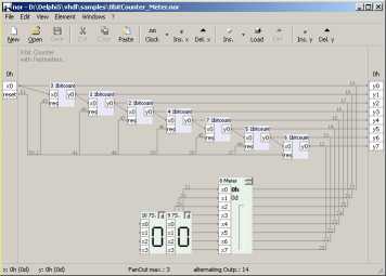 8bitCounter_meter.nor
Try a Doubleclick on one of the 1-bit-Counters or open its underlying
Circuit via Contextmenu ([Shift]-[F10] if current or Mouse-right-click)
to verify it's Content.
Repeatedly click on the external Input-Clamp "x0" on the left to
generate Input-Pulses and watch the State of the several
Countermodules. Each Counter divides your Clicking-Frequency by two and
passes it on to the next one.
View how the Outputdigits are 'filled up' from LSB (upper) to MSB
(lower).
The parallel switched Meter and 7-Segments-Display shows the
corresponding decimal respectively hexadecimal Values. If you intend to
use that Circuit in other Circuits don't worry about the additional
Displayelements, because in that case they will simply be ignored and
so do not disturb.
Notice: If you get bored in
clicking on the Input-Clamp let the Application doing that for you.
Open the "Clock"-Buttons-List  in the
Toolbar (or from Menu "Element/Clock-Events...") and choose one of the
offered Clock-Speeds. You will then asked what external Input-Value
should be used by the Clock-Timer (if that isn't defined yet). As the
ext. Input-Clamp you need is
the LSB (least significant bit) answer with "1". That Value as well as
an "Idle-Input-Value" and 10 further predefinable ext. Input-Values
obtainable by Keys [0] through [9] are stored in the
nor-Descriptionfiles.
in the
Toolbar (or from Menu "Element/Clock-Events...") and choose one of the
offered Clock-Speeds. You will then asked what external Input-Value
should be used by the Clock-Timer (if that isn't defined yet). As the
ext. Input-Clamp you need is
the LSB (least significant bit) answer with "1". That Value as well as
an "Idle-Input-Value" and 10 further predefinable ext. Input-Values
obtainable by Keys [0] through [9] are stored in the
nor-Descriptionfiles.
After doing that the ext. Inputclamps will repeatedly changing between
"0" and "1" until you click on the "Clock"-Button
or press Key [F4]. Restart it with another Click on the "Clock"-Button
or [F4].
Perhaps you now might want to have a Hardcopy/Printout
of your Circuit.
Use the appropriate Function from the "File"-Menu or press [Ctrl]+[P].
The resulting Preview can be printed or stored into the
MSWindows'-Clipboard for
use in other Applications.
A little hint for Teachers:
This is the fastest way to get Lesson-Worksheets.
Perhaps you remove some Wires/Connections in your Circuit and let your
Students fill it in to proof their Understanding. An example could be
the self-locking connections
in a simple Flipflop-Circuit. Recognizing
that Lack verifies explicitly the Understanding.
For Testing a given Connection click on an Input-Clamp with right
Mouse-Button. This will temporarily disconnect that Wire. Another
Right-Click on the same Clamp restores the former Connection. That
procedure may also be helpful to clear up the individual function of
each connection.
Example 10: RAM and Shiftregister,
LED-Display Content
Samplefile: Display.nor
This Step is to learn about two
different Storing-Units, the Memory with random Access (RAM) and the
serial Memory with either "Last-In-First-Out" (LIFO) or
"First-In-First-Out" (FIFO) behaviour. Both here offered Tool-Elements
"RAM 256x8" and "Shift-Register" bring with them the ability to display
their Contents.
Also you might get a first Idea on a 'programmable Machine' which could
lead to an Understanding of what a 'Processor' is doing.
For a first Glance get a blank Workspace and insert a "RAM 256x8"-Element.
Then widen it's built-in
Display to at least
eight or more 'Bytes' by
using the Up-/Down-Button on it's upper/left Edge. You should receive
an image as follows:
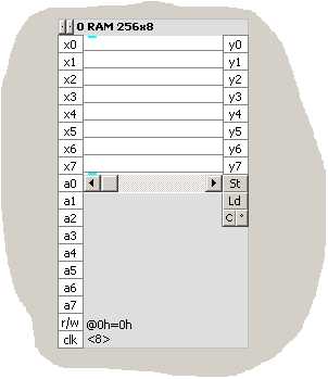
There are three Clamp-Sections on that Tool-Element:
- Clamps x0...x7: These Clamps must be set to the Value to
memorize
- Clamps a0...a7: These Clamps must contain the 'Address' into
which memorizing shall be done
- Clamps y0...y7: These Clamps will contain the Memories Output
Probably you now just know what to do. So lets attempt to store a Value
into our RAM what can hold ('address') 256 (2^8) different
memory-places each of 8 bit wideness.
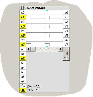
- At first set the Value-Input-Clamps (x0 through x7) to a Test-Value.
We use the decimal Value 170 that is in binary digits the nice Pattern
10101010 and in hexadecimal Notation AA. So you click on x1, x3, x5 and
x7 to set them "high".
- Then choose an Address where that Value should be stored. You have
256 Possibilities what means an Addressspace between 0 through 255. As
we just display only the first 8 Addresses simply let the
memory-Address keep on "0". (Otherwise use the Memory's Scrollbar if
necessary.)
- Now trigger the memorizing-Process by firing the "clk"-(Clock)-Clamp at the lower/left Edge with a
Mouseclick.
The Result should be the following:
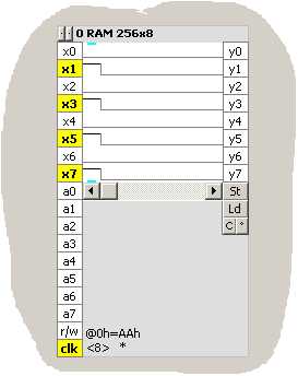
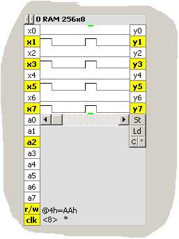
Just try another Address lets say 4 (what means that you set
Address-Clamp "a2" alone to "1"), leaving the Testvalue on AA and reset
and again set the "clk"-Clamp with that Result:
As you see, the "RAM 256x8"-Element displays it's Content in that case
like a Logic-Analyzer.
You can change the View by using the small Button  on the right to alternative Displaytypes for Example
into an LED-Rows-like one.
on the right to alternative Displaytypes for Example
into an LED-Rows-like one.
This was Writing into
the Memory. Now we finally need a Method to Read from it. Here it is:
- Reset the "clk"-Clamp to "low" ("0") by again clicking on it.
- Assume you need the Value stored at Address 4, so leave the
Address-Clamps unchanged.
- Fire the "r/w"-(read/write)-Clamp by Clicking on it to switch the
Memory from 'Writing' to 'Reading'.
- Click on the "clk"-Clamp what - due to the high-setted "r/w"-Clamp -
induces the RAM-Element to output (instead of storing) the Value
(170d[ecimal] or AAh[exadecimal] or 10101010b[inary]) stored at the
current Address (4d or 4h or 100b).
The Buttons labeled "St" and "Ld" on the RAM-Element enables you to
store (St) or to load (Ld) the RAM's Content
into/from a Text-File in hexadecimal
Notation thus using it as a Data-Recorder.
This is done in our Example
"Display.nor" to get Character-Patterns
from (in the Case of that Sample) a File "Characters.txt" which can be
viewed and edited with any ASCII-Texteditor like Windows' Notepad.
Additionally you can edit the RAM's-Content by simply doubleclicking on
a bit-Memory-Place what is currently shown on it's Display. A
right-Click on the Display will show the corresponding Byte-Value. The
both small Bars indicate current Writing-(blue) respectively
Reading-(green)-Address.
A nice Sample for becoming
familiar with the RAM-Element is Random.nor
which generates random Patterns in the RAM's Display.
It shouldn't be difficult for
you now to understand the other available Type of Memory-Element called
"Shift-Register".
Add one on your current Workspace for similar Testing and enlarge it
too with its Button on the upper/left Edge.
The main difference to the RAM is the lack of Addressability. All
incoming Values are stored 'as they come' either in forward Direction
(first-in-first-out, 'fifo') or in reverse Direction
(last-in-first-out, 'lifo')
depending on the Status of the "c/d"-(clear/direction)-Clamp. Setting the "c/d"-Clamp reverses the
Storing-Direction (at the bottom or at the top of the Memoryspace) and clears the Memory what can
also be done with the "C"-labeled-Button.
Hint for Teachers: It might be
a useful discourse to speak about 'Clearing' a Random-Access-Memory
which is obviously a matter of how the Status 'cleared' will be defined
in opposite to a Shift-Register which will be actual empty after
clearing.
Reading from the Shift-Register:
As soon as the Memory-Content reaches the right side of it's Display
(and therefore the Memories end) the next Storing-Operation will cause
two things:
- The Value at the Input-Clamps is stored as mentioned above and
- the last Value (at the End of the Content) will be applied to the
Output and rejected
unless the 'additional Memoryspace'-Checkbox
 is set.
If that Checkbox is set, Memory will only be limited by the Computers
Memory otherwise by the current Length of the Display adjusted by you.
With a Shift-Register-Element you can also store Values that are wider
than 8 bits.
Adjust that with the Up/Down-Button at the upper/right Edge.
The maximum Display-Width is 64 (for RAM and Shift-Register), the
maximum digitscount for a Shift-Register is 32. So with a
Shift-Register you can store for Example four 8-bit-Values at the same
Time. That is the Reason for the kind of Storage in the Textfiles in
hexadecimal Values.
Now its time to look at our Samplefile "Display.nor":
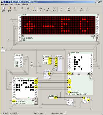 Display.nor
First, lean back and slowly analyze our apparent most complex Circuit
in that
small Tutorial.
It essentially consists of two
Shift-Registers, one to store the Text that should be
displayed, the other to show
that programmable Text like a LED-Display, and a RAM to hold the Character's
Patterns.
In the centerregion you see a
3-bit-Source, a 3-bit-Counter and a 3-bit-Comparer (doubleclick to see
their underlying Circuits) which gives an Event at it's Output-Clamp
"c0" each time the Counter equals the Value of the Source here 7. That
Output is used to shift the lower/left Shift-Register via it's
"clk"-(Clock)-Clamp to the next Characternumber giving the upper five
bits for the RAM's Address-Inputs.
The lower three Address-bits are added from the 3-bit-Counter to scan
the selected Character thus generating the Input-Signals for the
displaying, upper Shift-Register.
The high lower 1-bit-Source (Current
Source-Elements'
Output-Values are stored within the nor-Descriptionfiles) drives
the
r/w-(Read/Write)-Clamps to "Read"-State.
The other Elements are serving the "Programming-Modus". So if you want
to alter the displayed Text firstly shut off the Clock by [F4], then
set the Text-Memory to "Write"-State via the upper Single-Clamp (#52)
beneath the 5-bit-Source on the left. Set the appropriate Value of the
desired Character. With the second Single-Clamp (#92) trigger the
"clk"-Clamp so that your Character's Number is stored in the
Shift-Register. Finally set both Single-Clamps to "low" and restart the
Clock-Signal to display your new Text.
Hint for Teachers: Themes for
discourses might be the following questions:
- what must be changed to get other Characters?
- " to get wider/smaller Characters?
Example 11: Controlling external Hardware via the
Parallelport Content
Samplefile: PIO.nor
With the both Tool-Elements "Par.
Input" and "Par. Output" you can read and write from/to the
Standard-Lineprinter-Port (LPT1:) of your Computer. This works under
Windows-95/98 as well as under Windows-XP and is based on the DLL
IO.dll by Fred Bulback. The documentation for IO.dll can be found
at http://www.geekhideout.com/iodll.shtml. The accompanied DLL IO.dll is not an integral Part of that
Application - you can run nor
without IO.dll - and thus free of charge!
Use "Par. Input"- and "Par. Output"-Elements
for the most simplest way to control external Testhardware i.e. to
directly switch some connected LEDs.
Warning:
Connecting unsuitable
Hardware others than commercial Printers to the parallel Port of your
Computer can cause serious Damage of the internal or external
IO-Devices and thus requires full knowledge about the electrical
Context! You will do
so always on your own risk. Visit Fred Bulback's Site to get
further Information.
(Notice:
nor-Very-Simple-Logic-Simulator proofs only once, at it's very first start,
whether IO.dll can be processed properly. If that is not possible due
to
Machine- or System-Properties, nor will
store that fact in it's Configurationfile nor.ini which you will find in the
Applicationsfolder (that is by Default: C:\Program Files\ibh\nor) and
will not perform any further attempts to access the Parallel-Port.
If you want to access the
Parallel-Port yet in that case (only), you must change the Value of the
Entry "wio" to "1" in nor.ini.
Otherwise IO isn't accessible. In the opposite case, if you explicitly
want to suppress IO-Access
via IO.dll (which is working as kernel mode driver) set that Value to
"-1".)
"PIO.nor" shows how to read and write
from and to the Lineprinter's Port i.e. by generating Output-Data via a
Shift-Register-Element (in the Sample the Characters ABC and a
'Pagefeed'-Command (12d) will be send to the Printerport).
Data is sent respectively updated each time the "clk"-Clamp is set
"high".
Have a lot of fun.
Miscellaneous: Content
Statusbar
If you use external Clamps as in our first Example the Statusbar will in it's first section show the corresponding values in hexadecimal (h) and decimal (d) notation.
Also the Statusbar will announce "Fanout max." and "alternating Outp.".what can be interpreted as follows:
- Fanout max. gives you a hint on how much Inputs have to be provided by a Gate's-Output thus influencing the electrical Lay-out of a real Circuit. For example if you intend to realize your Circuit from an ASIC (Application-specified-integrated-Circuit) it might be advantageous not to have a lot of Gates with low Powerconsumption and only a few one with a high one due to high Fanouts. In that case you will probably spread Outputs by several "Driver"-Gates thus getting Gates with similar electrical Properties.
- Alternating Output shows to you how much Gates change their Status during last Inputevent. As if changing the Status costs Time due to the necessity of building up and down magnetic Fields (Inductivities) and to move electrical Charges (Capacities) you probably will lay out your Circuit having as less as possible Changes if you want to obtain high Performance (Frequencies).
Notice: That values won't be propagated through nested circuits.
Rules for embedded Files
References to embedded (nested) Files will be resolved in the following Order.
If a nested Filename is absolute then nor at first tries to open the desired File.
If it will not find that File then resolving is continued in the same way as a plain Filename using the Folders indicated in the Options-Window (Menu "File/Options") in the following Order:
- Path to the current Project(nor)file
- Projectpath
- Librarypath
- Projectlibrarypath
- Applicationpath
Options (Menu "File/Options")
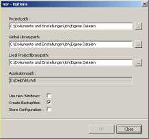
Additional Options
- Use new Windows: If selected the "New"-Button on the Toolbar or Menu "File/New" will bring up a new Window instead of blanking the current one.
- Create Backupfiles: If selected during Saving an existing nor-Description a Backup-File of the former Version will be created.
- Store Configuration: If selected all current Settings (see also Menu "View") will be saved automatically on leaving the Application. Otherwise this is done by choosing Menu "File/Store Configuration".
Menues
» home
Anbieterkennzeichnung: Ing-Büro Bechler 44143 Dortmund Düsseldorferstr.42 info@ebechler.de